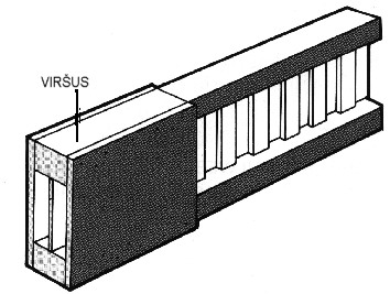
Beam is under bending load. This bending load causes:
DEFORMATION – vertical bend with respect to initial state.
BENDING FORCE – tensile and pressing stresses inside wooden bars.
PULL FORCE – comparative deflection between core and bars.

Bending under load at fixed length depends on:
- beam rigidity (beam rigidity depends on elasticity module, bars cross-section area and beam height as well);
- timber dampness (damp timber is inclined to higher deformations and begins to “shift” over longer periods);
- resilience of joints between core and bars.
PARAMETERS:
Elasticity module E= 10.000 N/mm²
Shift module C = 2.500 N/mm/1.500 N/mm
Resilience of joints C/e = 52,6 N/mm²/31,6 N/mm²
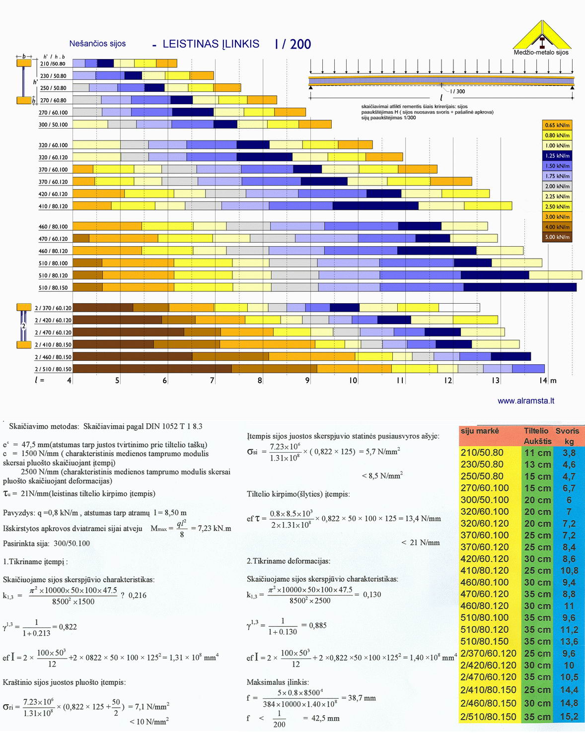
Calculations of NAILweb beams are carried out according DIN 1052 standard 1 st part 8.3 chapter. To check stresses C = 1500 N/mm must be considered and for bend checking C = 2500 N/mm must be considered. Distance between connection points e for single core beams is 47.5 mm and for double core beams is 23.75 mm.
The NAILweb beams have 1/300 bend, which is obtained during production.
ALLOWABLE BEND
According DIN 1 052 standard:
1/300, for functional load
1/200, for total load

The allowable bend of ceilings in administrative, residential buildings and in workshop and factories as well, is limited up to 1/300 even under total load.
Compensated BENDING MOMENT depends on cross-section of timber bars and on solidity of joint between bars and core as well.
ALLOWABEL STRESSES
Bending stress limit inside bar: allowable σ = 10 N/mm²
Center of gravity stress inside bar: allowable. σ = 8,5 N/mm²
(Softwood, II nd quality class)
Both timber bars of the beam are inclined to shift between each other. This causes STRETCH LOAD . Crossbar force is equal to support force at the bar tail supports.
The compensated crossbar force of NAILweb beams is limited by bearing power of joint between bars and core. The allowable split force at this joint is indicated in general building supervision license and depends on bar height:
ALLOWABLE SPLIT FORCE TRANSFER:
tmaks = 18 N/mm for bar height h = 36 mm
tmaks = 21 N/mm for bar height h > 46 mm
In between values can be deduced from linear function. The maximum allowable crossbar force can be calculated from the formula bellow:
Q = t maks. x ho where ho = distance between bars centers of gravity
Maximum total load of the beam with given height practically does not depend on beam length.
P = 2Q
EXAMPLE
37 cm height NAILweb beam with 60 mm height bars.
ho = 31cm, tmaks. = 21 N/mm
Q = 21 x 31 = 6,51 kN
T = 2 x Q = 13,00 kN
The maximum total NAILweb 370/60.100 load is limited to 13.00 kN
Bearing power of the crossbar force can be increased with additional means (see "Increase of bearing power").
Increase of bearing power
INCREASE OF COMPENSATED CROSSBAR FORCE INCREASE. The compensated total load of the NAILweb beam is limited by bearing power of joints between bars and core and practically does not depend on beam length. Compensated shift load is indicated in general building supervision license
Bearing power of the crossbar force can be increased using various means:
- By using 2 cores for one beam
(The allowable crossbar force is doubled);
EXAMPLE
Q = 8,61 kN for 47 cm height NAILweb beam
| ALLOWABLE CROSSBAR FORCE FOR BEAMS WITH 2 CORES |
| 2/370/60-100 |
13,0 kN |
2/410/80-120 |
13,9 kN |
| 2/420/60-100 |
15,1 kN |
2/460/80-120 |
16,0 kN |
| 2/470/60-100 |
17,2 kN |
2/510/80-120 |
18,1 kN |
- By using additional, external wooden cores at the points were crossbar force is exceeded.
Calculation of required core length to be stiffened
l = 0,50 (Q - Qallow.) L/Q
n = (Q - Qallow.) L/(ho allow.N1)
l = length of cores to be stiffened
Q = compensated crossbar force
Qallow. = allowable crossbar force
L = sbeam length
allow.N1 = allowable nail cutting force
EXAMPLE
Beam with single core 370/60.100, length between supports 5 m, total load 20,8 kN
Q = 20,8/2 = 10,4 kN for one support
1.Length of core to be stiffene l = 0,5 (10,4 - 6,51) * 5/10,4 = 0,93 m
2.Required number on nails 31 x 65 kiekis n = (10 400 - 6 510)/0,93 (0,310*375) - 31,3 = 32 = 32/2 = 16 nail for one side and bar.
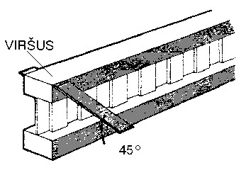
- By using external diagonal flat steel bars at the maximum crossbar force points.
This mean increases compensated crossbar force by 2.0 kN.
The diagonal bar 40 x 4 from st37, steel is mounted with two wavy nails 4,0 x 50 on every side.
HANGING OF LOADS ON LOWER BEAM
The allowable load on lower NAILweb beam bar with even load distribution (for example ceiling at the bottom etc.) is limited to:
Pu< 1,5 kN/m with load at separate points (for example: air-conditioner, sport equipment etc.)
Pu< 1,3 kN/m for one separate load point. If such separate load point is less than 0,5 m from the support, the allowable load Pu decreases by half. If loads are higher they must be distributed over upper bar. The allowable load on lower NAILweb beam bar with double core can be doubled.
CEILINGS IN BUILDINGS FROM TIMBER FRAMES
Construction of upper floor walls overload lower beams in buildings made of timber frames.
Ends of beams are pressed with local load.
Maximum allowable upper NAILweb beam bar pressing force is
at support:
- at end support: P = 5,0 kN
- at in-between support: P = 8,0 kN
If these values are exceeded both bars must be stiffened to avoid deeper penetration of core into the bars.

(If you wish to see a larger picture click on an image)
|
The distances between supports are calculated according these parameters:
|
- Weight and outside load on the beams (load H)
- Beam bend 1/300 (DIN 1052, T 1, 8,5,5)
|
to top